MHEWC Support in the Design and Installation of the National Situation Room to track multi-hazards
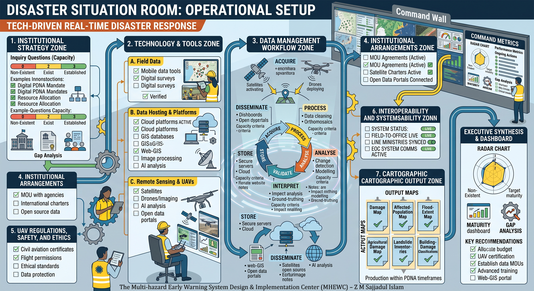
Design and Installation of the National Situation Room to track multi-hazards refers to a specific capacity-building initiative led by the Multi-hazard Early Warning System Design & Implementation Center (MHEWC), a global platform that supports early warning infrastructure in the Global South.
Because proprietary blueprints for specific national installations vary, developing a National Situation Room (NSR) or Emergency Operations Center (EOC) relies on a standardized, globally recognized framework aligned with the UNDRR (United Nations Office for Disaster Risk Reduction) and WMO (World Meteorological Organization).
Here is the detailed, five-Step technical blueprint for designing and installing a multi-hazard National Situation Room.
Step 1: Conceptual Design and Institutional Assessment
Before physical construction begins, the NSR’s operational scope must be defined based on the country’s specific hazard profile (e.g., cyclones, earthquakes, pandemics, industrial accidents).
Multi-Hazard Mapping: Identify all primary and secondary hazards. The design must accommodate data streams for hydro-meteorological, geological, and human-made threats.
Stakeholder Integration: Map the data flow from National Meteorological and Hydrological Services (NMHS), geological survey departments, and local emergency responders into the central NSR.
Legal and Mandate Framework: Establish the legal authority of the NSR. The room must have the statutory right to issue alerts, trigger the Common Alerting Protocol (CAP), and mandate evacuations.
Step 2: Physical Infrastructure Design
The physical space must be highly secure, self-sustaining, and ergonomically designed to support high-stress, 24/7 operations.
Site Selection: The facility must be located outside high-risk flood zones and fault lines. It requires reinforced, seismically isolated construction.
Spatial Zoning:
Main Operations Floor: Tiered or semi-circular desk layouts facing a central video wall for optimal sightlines.
Strategic Command Room: A glass-walled, soundproofed room overlooking the operations floor for executive decision-makers.
Server and Communications Room: A physically secured, climate-controlled IT hub.
Life Support Areas: Bunk rooms, kitchens, and showers to sustain staff during multi-day lockdown scenarios.
Infrastructure Redundancy: The facility must operate independently of the national grid. This requires N+1 redundancy (at least one independent backup for every critical system), including Uninterruptible Power Supplies (UPS), dual diesel generators, and redundant HVAC systems to prevent server overheating.
Step 3: Technological and Data Architecture
The technological backbone of an NSR transforms raw data into actionable intelligence.
| System Category | Core Technical Requirements |
| Visualization & Displays | Large-scale LED/LCD video wall, modular display controllers, and individual operator dual-monitor setups. |
| Communication Networks | VoIP, redundant fiber-optic lines, VHF/UHF radio base stations, and satellite communication (e.g., BGAN, VSAT) for grid failures. |
| Data Aggregation | Automated API ingestion from remote sensor networks (seismic gauges, weather radar, river telemetry). |
| Disaster Management Software | Geospatial Information Systems (GIS) dashboards, Impact-Based Forecasting (IBF) modules, and CAP-compliant alert distribution software. |
Step 4: Operational Framework and SOPs
Hardware alone cannot run a Situation Room. The installation process includes drafting strict Standard Operating Procedures (SOPs) for the staff.
Alert Thresholds: Establish objective triggers (e.g., “If river level exceeds X meters AND rainfall forecast is Y mm/hour, issue a Level 3 Warning”).
Role Definitions: Assign specific desks for Data Analysts, GIS Specialists, Inter-agency Liaisons, and Public Communications Officers.
Information Dissemination: Design the workflow for pushing alerts across multiple channels simultaneously (SMS, radio, television, sirens) through a single interface.
Step 5: Installation, Testing, and Commissioning
The final phase bridges the gap between construction and active deployment.
Hardware Installation and Networking: Physical mounting of the video walls, server racks, and routing of secure, air-gapped internal networks.
Software Configuration: Calibrating the GIS maps with local data (population density, critical infrastructure, road networks) and integrating live sensor feeds.
Conduct situation awareness technical training: Running simulated disaster scenarios (e.g., a Category 4 cyclone making landfall) to test both the hardware’s load capacity and the staff’s adherence to SOPs.
Final Commissioning: The formal handover of the fully operational NSR to the national disaster management authority, complete with maintenance schedules and continuous training roadmaps.
Design and Installation of a National Situation Room for Real-Time Multi-Hazard Monitoring, Early Warning and Coordinated Action
1. Purpose and strategic vision
The proposed National Multi-Hazard Situation Room NMHSR should serve as the country’s permanent, technology-enabled centre for collecting, integrating, analysing and visualizing information on existing and emerging hazards. It should provide national decision-makers, technical agencies, emergency managers and humanitarian partners with a continuously updated Common Operational Picture of hazards, exposure, vulnerability, likely impacts, early actions, emergency operations and resource requirements.
The Situation Room should operate continuously during normal conditions and shift progressively into an enhanced coordination mode when predefined hazard thresholds are reached. Its central purpose should be to answer:
What hazard or atmospheric anomaly is developing?
Where is it occurring or likely to occur?
When could it reach exposed areas?
How severe could it become?
Which people, infrastructure, ecosystems and economic activities are exposed?
What impacts are likely?
Which actions must be taken, by whom and within what timeframe?
Are warnings, early actions and response operations reaching the affected population?
A multi-hazard early-warning system must connect risk knowledge, hazard detection and forecasting, warning communication, and preparedness and response capacity. The Situation Room should provide the operational bridge linking these four pillars. WMO Multi-Hazard Early Warning Systems Checklist
2. Situation Room versus Emergency Operations Centre
The National Situation Room and the Emergency Operations Centre—EOC—may be housed in the same facility, but their functions should be clearly defined.
| National Situation Room | Emergency Operations Centre |
|---|---|
| Operates continuously during normal and emergency periods | Usually activated or scaled up when an emergency threshold is reached |
| Monitors hazards, forecasts, exposure, vulnerability and emerging risks | Coordinates operational response and resource mobilization |
| Maintains the national risk and hazard picture | Maintains the incident and response picture |
| Supports anticipatory decision-making | Supports command, coordination and operational decisions |
| Tracks early-warning indicators and activation thresholds | Tracks response actions, resources, logistics and unmet needs |
| Produces technical and decision-support briefs | Produces incident action plans and operational directives |
| Supports NMHS and sector agencies without replacing their mandates | Coordinates participating institutions under the national emergency framework |
The preferred approach is an integrated Situation Room–EOC model. Under normal conditions, the facility functions as a risk-monitoring and early-warning centre. During escalating emergencies, additional personnel and coordination cells are activated so that it functions as the information and coordination core of the national EOC.
ISO 22320 provides relevant guidance on incident-management structures, responsibilities, resource management, joint direction and interorganizational cooperation. ISO 22320:2018
3. Core objectives
The design and installation programme should enable the Situation Room to:
Monitor hydro-meteorological, geological, biological, environmental, technological and human-induced hazards.
Integrate real-time and near-real-time data from multiple institutions.
Maintain a national geospatial risk repository.
Detect anomalies and track evolving hazards.
Monitor thresholds and automatically flag deteriorating conditions.
combine forecasts with exposure, vulnerability and historical-impact information.
Generate impact-based risk scenarios.
Support early-warning, anticipatory-action and emergency-activation decisions.
Maintain a Common Operational Picture across national and subnational institutions.
Disseminate authorized warnings through multiple communication channels.
Track warning receipt, early actions, incident reports and response progress.
Support post-event impact, loss-and-damage and recovery assessments.
Archive data for lessons learned, research, planning and accountability.
4. Institutional and governance arrangements
4.1 Lead institution
The government should formally designate the institution responsible for hosting and operating the Situation Room. This may be:
The National Disaster Management Agency;
The Office of the Prime Minister or President;
The Ministry responsible for disaster management;
A National Emergency Management Authority; or
Another legally mandated national coordination institution.
The host institution must not duplicate or override the technical mandates of the National Meteorological and Hydrological Service, geological survey, health authority, environment agency or other technical bodies.
4.2 Legal mandate
The enabling legal or administrative instrument should define:
The Situation Room’s mandate;
Its relationship with the national EOC;
Participating ministries and technical agencies;
Authority to request and receive data;
Official hazard-monitoring and warning authorities;
Approval procedures for public warnings;
Information-classification and confidentiality requirements;
Emergency data-sharing obligations;
Activation and deactivation authority;
Authority for resource requests and operational coordination;
Rules governing international and transboundary data exchange; and
Accountability for system operation and maintenance.
4.3 National coordination committee
A multidisciplinary steering committee should oversee design, installation and operation. Membership should include:
National Disaster Management Agency;
National Meteorological and Hydrological Service;
Geological and seismic agencies;
Water-resources and river-basin authorities;
Ministries responsible for environment, agriculture, health, infrastructure, transport, energy and telecommunications;
Police, fire, civil defence and armed forces, as legally appropriate;
National mapping and space-research agencies;
Local-government representatives;
Mobile-network operators and broadcasters;
Humanitarian organizations;
Universities and research institutions;
Organizations of persons with disabilities;
Women’s and community-based organizations; and
Private technology and infrastructure operators.
4.4 Data-sharing agreements
Formal agreements should specify:
Which datasets each institution will provide;
Data formats, metadata and quality requirements;
Transmission frequency and latency;
API or database-access arrangements;
Ownership and permitted use;
Data-security classification;
Data-retention requirements;
Responsibilities for correcting erroneous data;
Cost-sharing arrangements; and
Procedures during communication outages.
5. Multi-hazard monitoring scope
The Situation Room should be configured around the country’s official national risk profile rather than using a generic hazard list.
5.1 Hydro-meteorological hazards
Tropical cyclones;
Severe thunderstorms;
Extreme rainfall;
Riverine, flash and urban flooding;
Storm surge and coastal inundation;
Lightning;
Hail;
Damaging surface winds;
Heatwaves and cold waves;
Drought;
Dust and sandstorms;
Heavy snow and blizzards;
Glacial-lake outburst floods; and
Marine and lake hazards.
5.2 Geological hazards
Earthquakes;
Tsunamis;
Volcanic activity;
Landslides;
Rockfalls;
Land subsidence;
Ground deformation;
Sinkholes; and
Coastal and riverbank erosion.
5.3 Biological and public-health hazards
Epidemic and pandemic outbreaks;
Water- and vector-borne diseases;
Crop pests and livestock diseases;
Food-safety emergencies;
Harmful algal blooms; and
Biological contamination.
5.4 Environmental and ecosystem hazards
Wildfires;
Air pollution;
Hazardous smoke;
Deforestation and ecosystem degradation;
Water contamination;
Salinity intrusion;
Wetland degradation; and
Marine pollution and oil spills.
5.5 Technological and human-induced hazards
Industrial accidents;
Chemical spills;
Dam failures;
Mine accidents;
Major transport accidents;
Urban fires;
Building collapse;
Critical infrastructure failure;
Energy-system disruption;
Cyber incidents affecting essential services; and
Population displacement and complex emergencies.
5.6 Compound and cascading hazards
The system must track interactions among hazards. Examples include:
Cyclone, storm surge, extreme rainfall and river flooding;
Earthquake, landslide, dam failure and downstream flooding;
Drought, crop failure, food insecurity and displacement;
Heatwave, wildfire, smoke and public-health emergencies;
Extreme rainfall, landslides, transport disruption and isolation;
Flooding, water contamination and disease outbreaks; and
Power failure, telecommunication disruption and interruption of emergency services.
6. Functional architecture
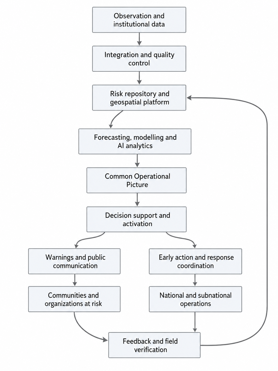
The architecture should consist of seven interconnected functional layers.
Layer 1: Observation and data acquisition
This layer receives information from:
Weather satellites;
Meteorological radar;
Automated weather stations;
Rain gauges;
Lightning-detection networks;
River and reservoir gauges;
Groundwater and soil-moisture sensors;
Ocean buoys and tide gauges;
Seismic and volcanic-monitoring stations;
Landslide and ground-movement sensors;
Air-quality stations;
Wildfire-detection systems;
Drones and aerial surveys;
Traffic and infrastructure-monitoring systems;
Health-surveillance systems;
Field-assessment applications;
Community-based observers;
Humanitarian organizations; and
Open international and regional data services.
Layer 2: Integration and quality control
The platform should automatically:
Receive data through APIs, message brokers, database replication, sensor gateways and file-transfer services;
Validate timestamps, locations, units and data ranges;
Identify missing, duplicated or anomalous observations;
Standardize geographic coordinates and administrative codes;
Harmonize data formats;
Record data lineage and metadata;
Flag poor-quality observations;
Log system and sensor outages; and
Notify the responsible institution when a feed fails.
Layer 3: National risk repository
A centralized geospatial repository should contain:
Administrative boundaries;
Settlements and population distribution;
Buildings and critical facilities;
Roads, bridges, airports, railways and ports;
Hospitals, health facilities and ambulance stations;
Schools, shelters and evacuation centres;
Power plants, substations and transmission networks;
Telecommunication infrastructure;
Water supply and sanitation systems;
Dams, embankments, drainage and irrigation systems;
Agricultural land and livelihood zones;
Forests, wetlands and protected areas;
Historical hazard events;
Recorded disaster losses and damages;
Hazard and susceptibility maps;
Exposure and vulnerability data;
Social-protection registries, with appropriate privacy controls;
Evacuation routes;
Emergency resources and stockpiles; and
Institutional contact directories.
The repository should support version control, metadata catalogues, access permissions, backup, audit trails and periodic updating.
Layer 4: Modelling and analytical services
The Situation Room should integrate or connect to:
Numerical weather-prediction products;
Nowcasting systems;
Flood and flash-flood models;
River-routing and inundation models;
Storm-surge and coastal-inundation models;
Drought-monitoring indices;
Wildfire-risk and smoke-dispersion models;
Landslide threshold and susceptibility models;
Earthquake shakemaps;
Tsunami-arrival and inundation models;
Epidemic-surveillance models;
Infrastructure disruption models;
Exposure and vulnerability models; and
Impact-based forecasting systems.
Artificial intelligence may assist with anomaly detection, data fusion, image interpretation, event classification and impact estimation. AI outputs must be labelled with confidence levels and should not automatically replace authorized expert judgment.
Layer 5: Common Operational Picture
The Common Operational Picture should display:
Current hazards and warnings;
Forecast hazard footprints;
Alert levels and confidence;
Exposed populations and assets;
Vulnerable groups and locations;
Critical facilities within potential impact areas;
Estimated severity and impact;
Evacuation zones and shelters;
Incident reports;
Road and infrastructure status;
Response resources and deployments;
Assistance requests;
Operational gaps and priorities;
Warning dissemination status; and
Time remaining before expected impact.
FEMA describes the EOC’s role as helping form a common operating picture, supporting coordination and relieving field command from external coordination burdens. FEMA guidance on EOC coordination
Layer 6: Decision-support and incident management
The system should support:
Threshold monitoring;
Automated escalation flags;
Incident creation;
Task assignment;
Action tracking;
Resource requests;
Situation reports;
Decision logs;
Meeting records;
Incident Action Plans;
Contact and duty-roster management;
Shift handover;
Map annotation;
Document management;
Photograph and video evidence;
Needs-assessment tracking; and
After-action review.
Layer 7: Warning and information dissemination
Warnings should be disseminated through multiple channels:
Common Alerting Protocol feeds;
Cell broadcast;
SMS;
Mobile applications;
Radio and television;
Websites and social media;
Email;
Sirens and public-address systems;
Satellite communication;
Emergency-service communication networks;
Community volunteers;
Local-government channels; and
Accessible services for persons with disabilities.
CAP provides a standardized format for exchanging all-hazard warnings simultaneously across multiple dissemination systems. OASIS Common Alerting Protocol 1.2
7. Physical design of the Situation Room
7.1 Site-selection criteria
The facility should be located outside, or adequately protected from:
Flood zones;
Storm-surge areas;
Landslide-prone slopes;
Seismically unsafe buildings;
Industrial-risk zones;
Major fire hazards;
Security-sensitive congestion; and
Single points of transport or communication failure.
The site should have:
Multiple access routes;
Proximity to key national institutions;
Reliable telecommunications;
Independent power and water;
Controlled entry;
Space for expansion;
Accessibility for persons with disabilities; and
A geographically separate backup facility.
7.2 Recommended functional zones
| Functional area | Primary purpose |
|---|---|
| Main operations floor | Continuous monitoring and multiagency coordination |
| Hazard-monitoring cell | Weather, flood, geological, health and environmental monitoring |
| GIS and risk-analysis cell | Mapping, exposure analysis and impact estimation |
| Incident-management cell | Tasking, resource tracking and operational coordination |
| Communications cell | Radio, telephone, satellite and warning dissemination |
| Executive briefing room | High-level briefings and strategic decisions |
| Media and public-information room | Coordinated public information and media briefings |
| Technical server room | Servers, storage, networking and cybersecurity equipment |
| Telecommunications room | Radio, satellite and telephony equipment |
| Secure meeting room | Restricted operational and security discussions |
| Training and simulation room | Staff training, exercises and system testing |
| Duty and rest area | Support for prolonged 24/7 operations |
| Equipment and document storage | Spare equipment, forms, maps and emergency supplies |
7.3 Main operations floor
The main floor should include:
Semi-circular or functional team-based workstation arrangement;
Clear sightlines to video walls;
Adjustable desks and ergonomic chairs;
Acoustic treatment;
Individual and team display monitors;
Integrated voice and data ports;
Controlled lighting;
Reliable air-conditioning;
Accessible pathways;
Secure cable management;
Separate spaces for technical monitoring and executive coordination; and
Capacity for surge staff during major emergencies.
7.4 Video wall
The video wall should display configurable layouts, including:
National hazard map;
Satellite and radar imagery;
Forecasts;
River and rainfall dashboards;
Incident locations;
Exposure and impact estimates;
News and verified social-media feeds;
CCTV or drone video;
Field-team locations;
Resource deployments;
Warning status; and
Telecommunications and system health.
The video wall should not be the core system. Every critical display must also be accessible through individual workstations and the backup facility.
8. ICT and geospatial infrastructure
8.1 Core platform components
The technical platform should include:
Web-based multi-hazard dashboard;
Enterprise Geographic Information System;
Spatial and non-spatial databases;
Data lake or data warehouse;
API gateway;
Sensor and Internet-of-Things integration platform;
Event-streaming or message-broker service;
Incident-management application;
Document-management system;
Mobile field-data collection;
Identity and access management;
Notification and CAP-authoring platform;
Analytical and modelling servers;
Backup and disaster-recovery systems; and
System-health monitoring.
8.2 Open and interoperable design
The platform should support:
RESTful APIs;
OpenAPI documentation;
Standard geospatial services;
GeoJSON and other common exchange formats;
Common Alerting Protocol;
Standard meteorological and hydrological formats;
Secure sensor messaging;
Role-based data access;
Multilingual interfaces; and
Integration with existing institutional systems.
The government should avoid dependence on one vendor by requiring data portability, documented APIs, ownership of configuration files and source-code access where appropriate.
8.3 Deployment model
A hybrid deployment is generally advisable:
On-premises systems for mission-critical operations;
Government or accredited cloud infrastructure for scalability and backup;
Edge gateways for remote sensors;
Replicated databases at a secondary location; and
Offline operational capability during internet disruption.
9. Emergency communications
The facility should maintain redundant communication through:
Fibre-optic internet;
A secondary internet provider using a separate route;
Government data networks;
Mobile networks from more than one operator;
VHF and UHF radio;
HF radio for long-distance backup;
Satellite phones and broadband terminals;
Secure video conferencing;
Hotlines to key institutions;
Mass-notification systems; and
Amateur-radio or other nationally approved backup arrangements.
The National Emergency Telecommunications Plan should define how communication services are maintained during mitigation, preparedness, response and recovery. ITU National Emergency Telecommunications Plan guidance
10. Power, environmental control and physical resilience
The Situation Room should include:
Dual utility-power feeds where available;
Online uninterruptible power supplies;
Automatic voltage regulation;
Backup generators;
Sufficient fuel for extended operation;
Solar power and battery storage where feasible;
Redundant cooling for the server and communications rooms;
Fire detection and clean-agent suppression for technical rooms;
Water-leak detection;
Lightning and surge protection;
Equipment grounding;
Seismic anchoring of racks and displays;
Environmental sensors for temperature and humidity; and
Preventive-maintenance schedules.
Power, cooling, internet and core servers should not contain unaddressed single points of failure.
11. Cybersecurity and data protection
A national Situation Room is critical infrastructure and should be protected accordingly.
Required controls include:
Network segmentation;
Zero-trust access principles;
Multi-factor authentication;
Least-privilege permissions;
Encrypted communication and storage;
Secure remote access;
Firewalls and intrusion detection;
Security information and event management;
Endpoint protection;
Vulnerability scanning;
Patch and configuration management;
Offline and immutable backups;
Security testing before commissioning;
Incident-response procedures;
Vendor-access controls;
Audit logs;
Data-retention schedules; and
Personal-data protection.
Public-facing dashboards, operational systems, sensor networks and classified information should be separated into distinct security zones.
12. Operational structure and staffing
12.1 Core positions
The permanent team should include:
Situation Room Director;
Operations Manager;
Duty Officers;
Hazard-Monitoring Specialists;
Meteorologist or NMHS liaison;
Hydrologist or water-agency liaison;
Geological-hazard liaison;
Public-health liaison;
GIS and Remote-Sensing Specialists;
Risk and Impact Analysts;
Data Engineers;
Database Administrators;
ICT and Network Engineers;
Cybersecurity Specialists;
Emergency Communications Officers;
Public Information Officers;
Logistics and Resource-Tracking Officers;
Documentation and Reporting Officers; and
Administrative and facility-support personnel.
12.2 Surge staffing
During major events, representatives from relevant ministries, local governments, utility providers, humanitarian organizations and response agencies should join through physical deployment or secure virtual participation.
12.3 Duty arrangements
The Situation Room should maintain:
A 24/7 duty roster;
Defined shift duration;
Shift-handover checklists;
On-call technical specialists;
Backup staffing;
Fatigue-management measures;
Contact directories; and
Procedures for rapid staff mobilization.
13. Activation levels
A standardized activation framework may include:
| Level | Operating condition | Typical action |
|---|---|---|
| Level 0 – Routine | No significant threat | Continuous monitoring, maintenance and daily reporting |
| Level 1 – Advisory | Hazard indicators require attention | Enhanced monitoring and technical consultation |
| Level 2 – Watch | Credible threat within an operational timeframe | Multiagency notification, scenario analysis and readiness checks |
| Level 3 – Warning | Significant impact is likely or occurring | Partial EOC activation, warning dissemination and early action |
| Level 4 – National emergency | Severe or widespread impacts | Full EOC activation and national coordination |
| Recovery monitoring | Immediate threat declining | Damage tracking, service restoration and recovery coordination |
Activation criteria should be hazard-specific and based on authorized forecasts, thresholds, likely impacts and operational lead time.
14. Standard operating procedures
The operational package should include SOPs for:
Routine monitoring;
Data validation;
Sensor and data-feed failure;
Threshold escalation;
Incident verification;
Situation Room activation;
EOC activation;
Technical briefing preparation;
Impact-based forecasting;
Public-warning authorization;
CAP message preparation;
Media communication;
Early-action activation;
Evacuation coordination;
Resource requests;
Field-information verification;
Shift handover;
cybersecurity incidents;
Power and telecommunications failure;
Backup-site activation;
Fatality and sensitive-information handling;
Situation-report production;
Deactivation;
After-action review; and
Data archiving.
Every SOP should specify the trigger, responsible officer, approving authority, required inputs, action sequence, completion timeframe, communication channel and documentation requirement.
15. Design and installation methodology
Phase 1: Assessment and requirements definition
Assess existing institutional mandates and coordination mechanisms.
Review national hazard, exposure and vulnerability profiles.
Inventory existing sensors, databases, dashboards and communication systems.
Assess current EOC and Situation Room capacity.
Identify user groups and decision requirements.
Undertake building, power, network and cybersecurity assessments.
Complete a capacity-needs and training-needs assessment.
Prepare functional and technical requirements.
Phase 2: Conceptual and detailed design
Develop the Concept of Operations.
Prepare the institutional and data-governance framework.
Design the physical layout.
Develop system and network architecture.
Specify hardware, software, furniture and communications equipment.
Prepare bills of quantities.
Develop data models and integration specifications.
Prepare environmental, electrical and security designs.
Develop the business-continuity and backup-site design.
Phase 3: Procurement
Procurement documents should define:
Functional requirements;
Minimum technical specifications;
Interoperability requirements;
Equipment warranties;
Installation and configuration responsibilities;
Data-ownership provisions;
Cybersecurity requirements;
Training obligations;
Documentation;
Spare parts;
Service-level agreements;
Maintenance and support periods; and
Acceptance-testing criteria.
Phase 4: Civil and technical installation
Renovate and secure the physical facility.
Install electrical, backup-power and grounding systems.
Install HVAC and fire-protection systems.
Install structured cabling.
Establish server and telecommunications rooms.
Install network and security equipment.
Install workstations, displays and video walls.
Install radio and satellite communications.
Configure databases, software and dashboards.
Integrate institutional and sensor data feeds.
Configure the backup facility.
Phase 5: System integration
Connect hazard-monitoring feeds.
Load base maps and risk datasets.
Integrate forecasting and modelling platforms.
Configure hazard thresholds.
Configure user roles and permissions.
Establish CAP warning workflows.
Configure automated reporting.
Connect national and subnational EOCs.
Establish interfaces with telecommunications operators and broadcasters.
Phase 6: Testing and commissioning
Testing should cover:
Hardware functionality;
Network performance;
Data-feed reliability;
Database replication;
Dashboard accuracy;
Geospatial processing;
User-access control;
Cybersecurity;
Power failure and generator transfer;
Internet and telecommunications failure;
Backup-site operation;
Warning-message generation;
Multiagency incident simulation; and
Full 24/7 operational endurance.
No system should be accepted solely on the basis of equipment delivery. Acceptance should require successful operational testing under realistic emergency scenarios.
16. Training and simulation
Training should include:
Situation Room management;
Multi-hazard monitoring;
GIS and dashboard operation;
Data interpretation;
Impact-based forecasting;
Incident-management procedures;
Emergency telecommunications;
CAP message preparation;
Cybersecurity;
Media and risk communication;
Inclusive warning dissemination;
Shift management;
Business continuity; and
After-action review.
Exercises should progress through:
Orientation seminars;
Technical drills;
Tabletop exercises;
Functional exercises;
Communication-failure exercises;
Multiagency simulations; and
Full-scale national exercises.
17. Performance and acceptance indicators
The Situation Room’s performance should be measured through indicators such as:
Percentage of priority hazards monitored;
Percentage of required institutional data feeds connected;
Data-feed uptime;
Time required to detect feed failure;
Time from hazard detection to technical briefing;
Time from authorized warning to dissemination;
Percentage of warnings using CAP;
Percentage of the population covered by multiple warning channels;
Accuracy of geospatial exposure estimates;
Percentage of incidents with complete decision logs;
System and platform availability;
Backup restoration time;
Number of trained and certified personnel;
Number of simulations conducted annually;
Percentage of corrective actions implemented after exercises; and
User satisfaction among national and subnational institutions.
The EW4All monitoring framework can support alignment between Situation Room indicators and broader national early-warning outcomes. WMO Early Warnings for All Monitoring and Evaluation Toolkit
18. Sustainability and recurrent financing
The project budget must extend beyond construction and initial equipment. Recurrent financing should cover:
Staffing and 24/7 duty allowances;
Electricity, fuel and connectivity;
Software subscriptions and licenses;
Cloud and data-hosting services;
Hardware replacement;
Sensor maintenance;
Cybersecurity services;
Database updating;
Technical support;
Training and simulations;
Backup-facility maintenance; and
Periodic modernization.
A five- to ten-year technology-refresh and lifecycle-management plan should be approved before commissioning.
19. Expected result
The completed National Multi-Hazard Situation Room should function as a resilient, interoperable and continuously operating national hub for:
Multi-hazard detection and monitoring;
Atmospheric and surface-risk intelligence;
Forecast and warning integration;
Geospatial risk analysis;
Impact-based forecasting;
Anticipatory-action decision support;
Emergency activation and coordination;
Warning dissemination;
Incident and resource tracking;
Loss-and-damage information management; and
Recovery monitoring.
The result should not be merely a room containing computers and display screens. It should be an integrated national capability combining institutional mandates, skilled personnel, observation systems, risk data, forecasting, ICT infrastructure, interoperable communications, SOPs, decision authority and sustainable financing to transform hazard information into timely and accountable protective action.